 PluBIM Help
Modify
Rotate fittings, assign or clear systems, set slopes and spacing, align, disconnect components and cut out sections.
- Ribbon group
- ModelKit
- Version
- PluBIM 1.5.0
The Modify group on the PB-Modeling tab changes existing runs and components.
| You want to … | How |
|---|---|
| Rotate a fitting, a chain or a group of components about its axis | Rotate |
| Give pipes or ducts a different system | SetSystem |
| Remove the systems of elements | ClearSystem |
| Give runs a slope | SetSlope |
| Arrange elements at an even spacing | SetSpacing |
| Line up couplings or accessories | AlignParts |
| Remove connections between elements | Disconnect and DetachAll |
| Cut a piece out of a run | CutSection |
Which elements?
| Command | Works with | Not for |
|---|---|---|
 Rotate |
Fittings with at least two ports; a previously selected chain or group of components made of runs and fittings | Pinned elements; crosses without ports in line, fittings with more than four ports |
 SetSystem |
Elements with pipe or duct connectors: runs, fittings, accessories and equipment | Conduits, cable trays; pinned elements |
 ClearSystem |
Runs, fittings, accessories, mechanical equipment and plumbing fixtures | Elements without a system |
 SetSlope |
Straight pipes, ducts and conduits; a connected chain is graded end to end | Steep runs over 10° (they keep their angle); loops |
 SetSpacing |
Runs, fittings, accessories, mechanical equipment and plumbing fixtures | Elements held in place by constraints |
 AlignParts |
Fittings and accessories of pipes, ducts, conduits and cable trays with two ports in line, e.g. couplings and valves | Elbows |
 Disconnect,  DetachAll |
Runs, fittings, accessories, mechanical equipment and plumbing fixtures | Elements without connections |
 CutSection |
Straight pipes, ducts, conduits and cable trays | Curved runs; placeholders |
Rotate
Rotate turns a fitting about the axis of the run it sits on, e.g. an elbow, so the outlet points in a different direction. A previously selected chain or group of components made of runs and fittings rotates as a whole.
Click PB-Modeling › Modify › Rotate.
Click the fitting. If a chain or group of components is selected, click the straight piece that serves as the axis instead.
In the Rotate window, click an angle under Rotate by: the fitting rotates at once. Or enter a value under Free angle and click Apply. Each click rotates again by that angle. Negative values rotate clockwise.
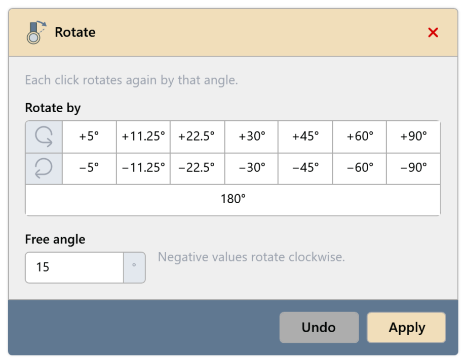
Fig. 2 · Rotate window Undo reverts the last rotation. When the position is right, close the window with Esc or the X at the top right.
SetSystem and ClearSystem
SetSystem changes the system type of pipes or ducts. ClearSystem removes the systems of the selected elements. They share one button; the small arrow below it switches to ClearSystem.
SetSystem
Click PB-Modeling › Modify › SetSystem.
In the SetSystem window, choose the Domain (Pipes or Ducts), then the System type.
Under Selection source, choose which elements are changed: Current selection / pick in Revit or a saved selection filter of the project.
To give the whole connected network the new system, turn on Include connected network.
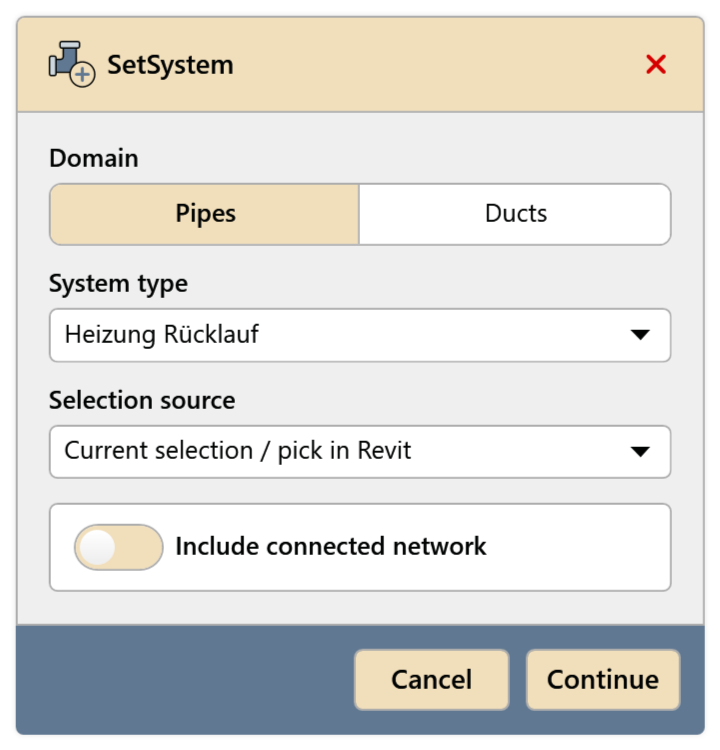
Fig. 3 · SetSystem window Click Continue. If nothing is selected, click the pipes or ducts and click Finish.
If the change of system would break a connection or change a connector outside the selection, SetSystem changes nothing and reports the reason. Then turn on Include connected network or separate the network first.
ClearSystem
- Select the elements and click PB-Modeling › Modify › ClearSystem. Without a selection, click an element.
SetSlope
SetSlope gives straight pipes, ducts and conduits a slope. A connected chain is graded end to end; the fittings in between follow.
Click PB-Modeling › Modify › SetSlope.
In the Set slope window, click a slope from the project values or enter one in % under Free slope. Click Continue.
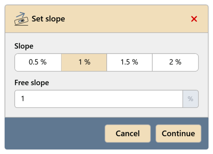
Fig. 5 · Set slope window If nothing is selected, click the runs and click Finish.
Click the run near the end that should be lowest.
SetSpacing
SetSpacing arranges elements at an even spacing on both sides of a fixed reference element, e.g. parallel runs.
Click PB-Modeling › Modify › SetSpacing.
Click the fixed reference element. It stays where it is.
In the SetSpacing window, choose the Measure (Center to center or Edge to edge) and enter the Spacing. Click Continue.
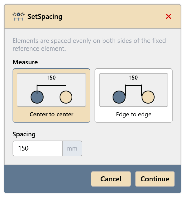
Fig. 7 · SetSpacing window If nothing is selected, click the elements to arrange and click Finish.
AlignParts
AlignParts moves couplings and accessories along their runs until they line up with a reference part. It is all or nothing: if one cannot be moved, AlignParts changes nothing.
Click PB-Modeling › Modify › AlignParts.
Click the reference coupling or accessory.
Click the parts to align and click Finish.
Disconnect and DetachAll
- Disconnect separates elements from each other. If elements are selected, only the connections between them are removed; connections to other elements stay. If one element is selected, click the second; if nothing is selected, click both.
- DetachAll removes every connection of the selected or clicked elements.
The elements stay where they are.
- Select elements and click PB-Modeling › Modify › Disconnect or DetachAll, or start without a selection and click the elements.
CutSection
CutSection cuts a piece out of a straight run between two points, e.g. to make room for a component.
Click PB-Modeling › Modify › CutSection.
Click the first point on the run. As you move the mouse, a preview shows the cut.
Click the second point on the same run.
Common problems
“This fitting has no usable rotation axis (more than four ports, or no ports in line).”
Rotate only turns fittings whose ports form an axis. Choose a different fitting, a chain or a group of components.
“Some selected elements are pinned. …” / “The selected element is pinned. …”
Unpin the elements and run the command again.
“The selection contains runs that are not connected. …” / “The selected runs form a loop, …”
SetSlope needs one connected run without a loop. Make the selection smaller.
“Constraints prevented the spacing. Nothing was changed.”
An element is held by a constraint (e.g. a locked dimension). Remove the constraint.
“The accessories could not be aligned. …”
There is not enough room in the run to move them, e.g. because a fitting is in the way.
“An end of the run moved while removing the section. Nothing was changed.”
The piece cannot be cut out at this point without moving the run. Place the points somewhere else.