 PluBIM Help
Routing
Model branches, bypasses and connections between runs, draw rows of runs and extend runs.
- Ribbon group
- ModelKit
- Version
- PluBIM 1.5.0
The Routing group on the PB-Modeling tab routes runs around obstacles, connects runs to each other and creates new runs.
| You want to … | How |
|---|---|
| Connect a run to a main at the chosen angle | AutoBranch |
| Route runs over, under or past an obstacle | VertOffset and SideOffset |
| Connect two round runs in different planes | OffsetLink |
| Connect two round runs in one plane | AngleRoute |
| Connect a pipe above a main from the top | DropBranch |
| Create several parallel pipes along a path | PipeArray |
| Extend runs to a wall, a grid or another run | ExtendTo |
Which elements?
| Command | Works with | Not for |
|---|---|---|
 AutoBranch |
Straight, unpinned pipes and round ducts; pipe to pipe or round duct to round duct | Rectangular and oval ducts, conduits, cable trays |
 VertOffset |
Straight, parallel pipes, ducts, conduits and cable trays, not pinned | Curved runs; runs that are not parallel |
 SideOffset |
Like VertOffset | Vertical runs |
 OffsetLink |
Two straight, round runs (pipes, round ducts, conduits), perpendicular to each other, in different planes, with the same slope | Rectangular ducts, cable trays |
 AngleRoute |
Two straight, round runs of the same category in one plane; the ends closest to each other are open | Runs in different planes (use OffsetLink) |
 DropBranch |
Pipes: a main and a pipe above it, perpendicular to it | Ducts, conduits, cable trays |
 PipeArray |
New pipes along a drawn path or previously selected straight lines | Paths with arcs or splines, branched or closed paths |
 ExtendTo |
Straight pipes, ducts, conduits and cable trays; the target is a face, edge, grid, level or another element | Ends that are already connected |
The fittings come from the routing preferences of each run type.
AutoBranch
AutoBranch connects a run to a main at the chosen angle and creates the stub, elbow and junction for it.
Click PB-Modeling › Routing › AutoBranch. A small window opens.
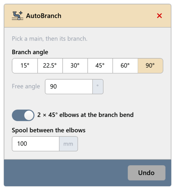
Fig. 2 · AutoBranch window Under Branch angle, choose or enter an angle.
Click the main, then the branch run.
Click more pairs. Undo reverts the last one created. Finish with Esc or the X at the top right; everything created stays.
At 90°, you can turn on 2 × 45° elbows at the branch bend: instead of one 90° elbow, two 45° elbows are created, with the entered Spool between the elbows in between.
VertOffset and SideOffset
VertOffset routes runs over or under an obstacle, SideOffset routes them past it sideways. Both share one button; the small arrow below it switches to SideOffset.
Select one or several parallel runs and click PB-Modeling › Routing › VertOffset or SideOffset. Without a selection, click the runs and click Finish.
Click the first and second point of the bypass on the run.
In the window, enter the Bend angle and the Vertical offset or Side offset. For VertOffset, positive values route over the obstacle, negative values under it. For SideOffset, the window says which direction positive values go.
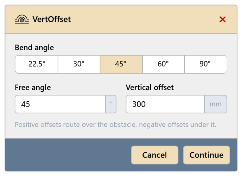
Fig. 4 · VertOffset window Click Continue.
Between the two points, all selected runs route around the obstacle together; the spacing stays the same.
OffsetLink
OffsetLink connects two round runs that lie perpendicular to each other in different planes with a rolling connection.
Click PB-Modeling › Routing › OffsetLink. A small window opens.
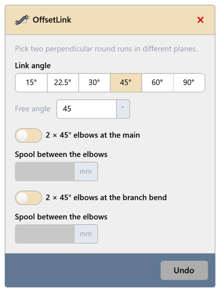
Fig. 6 · OffsetLink window Choose the Link angle.
Click the first and second round run.
Click more pairs. Undo reverts the last one created. Finish with Esc or the X at the top right; everything created stays.
Options in the window: 2 × 45° elbows at the main with Spool between the elbows, and at 90° 2 × 45° elbows at the branch bend.
AngleRoute
AngleRoute connects two round runs in one plane at the chosen angle.
Click PB-Modeling › Routing › AngleRoute. The window is like the AutoBranch window (Fig. 2), with Bend angle instead of branch angle.
Choose the Bend angle.
Click the first and second run. The ends closest to each other are connected.
Click more pairs. Undo reverts the last one created. Finish with Esc or the X at the top right; everything created stays.
If the first run has no system, AngleRoute reports “Assign a system type to the first run before connecting.”
DropBranch
DropBranch connects a pipe that crosses above a main from the top: through a 90° elbow and a 45° wye.
Click PB-Modeling › Routing › DropBranch. A small window with 2 × 45° elbows at the branch bend and Spool between the elbows opens.
Click the main near the side where the branch should be.
Click the pipe above the main.
Click more pairs. Undo reverts the last one created. Finish with Esc or the X at the top right; everything created stays.
PipeArray
PipeArray creates several parallel pipes along a path, e.g. a pipe rack.
Click PB-Modeling › Routing › PipeArray. If straight model lines are selected beforehand, PipeArray uses them as the path.
In the PipeArray window, choose Run type, DN and System type for each run. Add run adds a row, up to 5 runs; the trash can removes a row.
Enter Reference level and Elevation, then Arrangement (Side by side or Stacked), Elevation alignment (Top, Center, Bottom) and Spacing (from Center to center or from Edge to edge). The Sketch shows the arrangement.
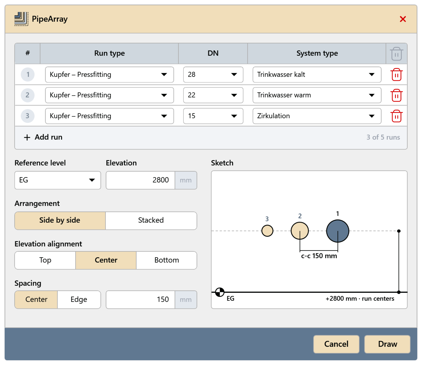
Fig. 10 · PipeArray window Click Draw. Draw the path from connected straight lines with Revit's line tool. If lines were selected, the button says Create and the pipes are created at once.
In the Draw path window, the counter shows the lines drawn. Click Finish: the pipes are created along the path. Esc only ends drawing mode; Draw resumes it, Cancel discards the path.
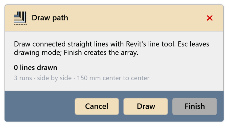
Fig. 11 · Draw path window
The path is drawn in a floor plan or an unlocked 3D view without perspective. It must consist of connected straight lines, without branches and without a closed loop.
ExtendTo
ExtendTo extends runs straight along their axis to a target. Parallel runs end on one line. Runs are never shortened, and no fittings are created.
Select the runs and click PB-Modeling › Routing › ExtendTo. Without a selection, click a run.
Click the target: a face, edge, grid, level or another element.
Without a selection, it continues with the next run. Finish with Esc.
Common problems
“The selected runs are not in one plane. …”
AngleRoute only connects runs in the same plane. For runs at different heights, use OffsetLink.
“The runs do not meet at the chosen angle. …”
Extend one run or choose a different angle.
“Increase the bypass offset: it must exceed Revit's minimum run length (at least 2.54 mm).” and similar messages for VertOffset
The offset or the distance between the two points is too small for the elbows. Increase the offset, move the points farther apart or change the bend angle.
“SideOffset needs non-vertical runs. …”
Bypass vertical runs with VertOffset, or select horizontal runs.
“AutoBranch supports round ducts only.”
AutoBranch connects pipe to pipe or round duct to round duct.
“The run does not point at the target, so it would get shorter. …” / “The end that faces the target is already connected.”
ExtendTo only extends the open end that points at the target. Choose a different target or disconnect the end first.
“No fitting could be placed. …”
A matching elbow or junction is missing in the routing preferences of the run type. Load the family and add it.